Create and configure VLANs in packet tracer
We will create VLAN 10 and VLAN 20 in this lab. It is always a good practice to give names to the VLANs as this makes it easier for the admins to manage configured VLANs. The best way to give a name is according to their role in the network e.g. if there is a VLAN that handles traffic for the voice of IP then we can give the name ‘voice’ to the VLAN and another way of assigning a name is according to the departments in the organization like Sales, marketing, etc.
In a case of a network outage or any issue with the VLANs, admins can easily identify the VLANs with names, which makes their work easier
We can use the following command to create VLAN 10 and 20 and give them a name.
Switch(config)#vlan 10
Switch(config-vlan)#name Voice
Switch(config)#vlan 20
Switch(config-vlan)#name Sales
Once we are done creating the VLANs, we can check the created VLANs with the command ‘show VLAN’
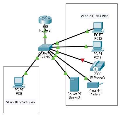
Assigning ports to VLAN
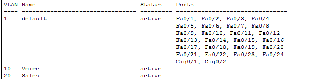
You can see in the image above that although we have created the VLANs however to use those VLANs, we have to assign ports to VLAN. By default, all ports are assigned to VLAN 1
We will assign 1 port to VLAN 10 and 5 ports to VLAN 20
If we want to assign multiple ports to a single VLAN then we can use the interface range command and include the range of ports that we want to add to any VLAN
Switch(config)#interface fastEthernet 0/1
Switch(config-if)#switchport mode access
Switch(config-if)#switchport access vlan 10
Switch(config)#interface range fastEthernet 0/2 – 6
Switch(config-if-range)#switchport mode access
Switch(config-if-range)#switchport access vlan 20
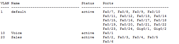
Now, we can see in the image below that assigned ports are appearing in front of VLAN 10 and 20
Inter VLAN routing in packet tracer
Each VLAN represents a separate network so to enable routing from one VLAN to another VLAN; we have to either use a layer 3 switch or a router.
On a single router interface, we can create sub interfaces and configure those interfaces to accept traffic from specific VLANs so we can use only one interface that is connected to the switch for routing purposes.
After configuring the sub-interfaces, we have to assign a default gateway on the end device so the default gateway would be the IP address of the sub-interface specified for the same VLAN of the end device.
Now the traffic will travel within the switch when communicating with the end device in the same VLAN and traffic will travel through the router when communicating with devices on other VLANs.
Please check router on a stick lab to properly configure inter VLAN routing.